 English
 Italiano
 Español
2016 to 2021 – Perth, Western-Australia
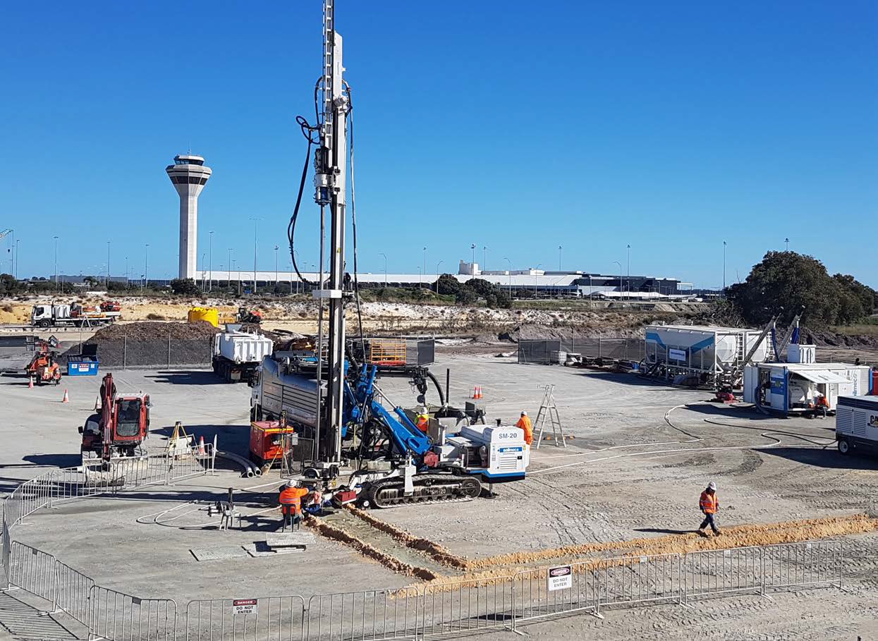
The Forrestfield Airport Link in Perth is a A$1.9B project that will deliver an 8.5 km extension of the existing urban rail network connecting the Midland Line, just past Bayswater Station, toHigh Wycombe, running underground in twin bored tunnels underneath the Swan River, Tonkin Highway and Perth Airport.
In April 2016 the Public Transport Authority awarded the design, construct and maintenance contract to Salini-Impregilo (now WeBuild) – NRW Joint Venture.
The project comprises the design, construction and maintenance for 10 years of the Forrestfield-Airport Link, which will connect the growing eastern suburbs of Perth with the existing suburban rail network as well as the airport. In the first year of operations the Airport Line is expected to generate 20,000 passengers trips on the network every day, as well as reduce road traffic and travel times.
The Project
The project works:
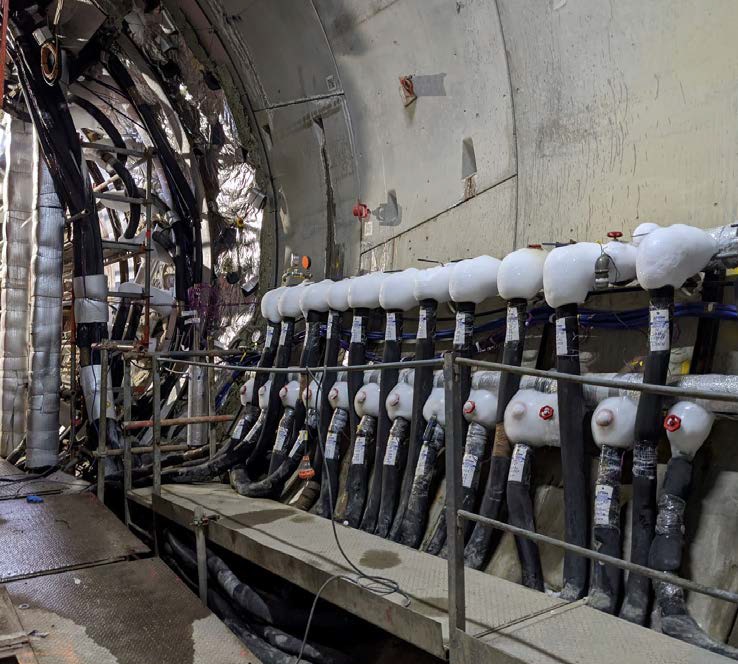
– 7.14 km of twin underground rail tunnels, with an external diameter of approximately 7 m. The tunnel separation, measured from the centre of one tunnel to the centre of the other tunnel, typically varies between 13 m and 15 m with a maximum depth Ground Level-Rail Level of about 32m;
– Three new railway stations:
• Redcliffe Station,
• Airport Central Station,
• Forrestfield Station,
– Two dive structures, at Bayswater and Hig Wycombe;
– Twelve Cross Passages;
– Three Emergency Egress Shafts.
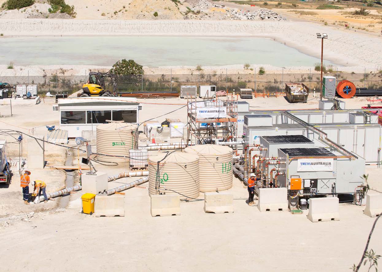
Trevi scope of works
Jet Grouting
The Jet Grouting soil improvement technique was an allotted work for Trevi Australia.
The scope of work includes the installation of jet grouted columns to create a consolidated block in correspondence with the cross passages, having both structural and hydraulic purposes, in order to allow the safe excavation of the connecting tunnels.
All JG columns were set in place prior to the passage of the TBM using both double fluid system, where the grout jet is assisted by an air shroud, and single fluid system, where only high-pressure grout is used.
The diameters achieved were 2.2 m and 1.0 m respectively.
The jetting-drill string was composed of specially designed rods with two concentric coaxial, the inner for high-pressure grout and the outer for compressed air.
Pre-washing (or pre-cutting) technique, in which water is used to pre-erode the soil, was performed either during the drilling phase or in a separate phase prior to jetting. Maximum installation depth was up to 32 m using a triangular grid spacing from 1.35 m to 1.75 m, according with the column diameters and depths of the treatment.
Prior to execution of the JG works three Field Tests were carried out in order to:
– Test the effectiveness of the JG Parameters and methodology
– Set the operating modalities
– Acquire data to optimize the work methodologies
To produce the most reliable data, the trials were carried out according to the project technical specifications in areas and at depths where the geology reflects as much a s possible the characteristics of the soil to be treated.
The trials were carried out with different sets of JG parameters and subsequent post installation tests including Coring, UCS and Modulus lab tests, Sonic Logging Testing and Permeability tests.
There were six Cross Passages (CP) and two Emergency Egress Shafts (EES) where Jet Grout treatment was required, as listed below:
– CP01 Tonkin; – EES Wright Crescent;
– CP05 Brearley; – CP06 Car Park C;
– CP10 Manheim; – CP11 RAC;
– EES Abernethy; – CP12 Dundas.
Dundas was the first location of the JG production works. The JG treatment within the Bassendean Sand from approximately 7 to 18 meters deep was quite superficial.
The particularity of the treatment was the geometry with the installation of inclined columns of up to 36 degrees from vertical and the use of the mono-fluid system for the columns with a greater inclination.
These solutions were implemented due to the presence of a gas pipe line and Fiber Optic Cabling in close proximity to the treatment area.
During execution of JG works a dedicated monitoring system was in place to ensure a safe working-condition and to avoid any damage to these utilities.
As in CP10 Manheim, CP06 Car Park C and also in CP05
Brearley AV a top layer of very fine sand was encountered which influenced the treatment by the impossibility to use the Pre-Washing technique due to the risk of forming sink holes on the surface.
To reduce the risk of collapsing and overturning of the rig two actions were adopted:
– Removal of the Pre-Washing phase, to reduce the siphoning effect
– A Pre-Treatment phase with mono-fluid columns, this to consolidate the upper portion of the ground assuring the stability of the working platform.